Design Setup & FAQ
We appreciate that creating your first laser cut part can be intimidating so we have compiled some advice to aid your design work.
Supported File Types
We can accept many common design file types as below:-
 |
CorelDRAW (*.cdr, *.eps) |
 |
Adobe Illustrator (*.ai) |
 |
Inkscape (*.svg) - (Free) |
 |
Solidworks (*.dxf, *.slddrw) |
 |
AutoCAD (*.dxf) |
If you don’t have drawing software that exports to one of the above file types (a VECTOR format) please email us before placing an order so we can check your requirement (in some instances we can help generate simple designs). Note that Inkscape is available online as FREE SOFTWARE.
File Formatting
Our product pages give an instant price inclusive of material and cutting. To ensure your order is accepted and processed promptly please ensure the following formatting.

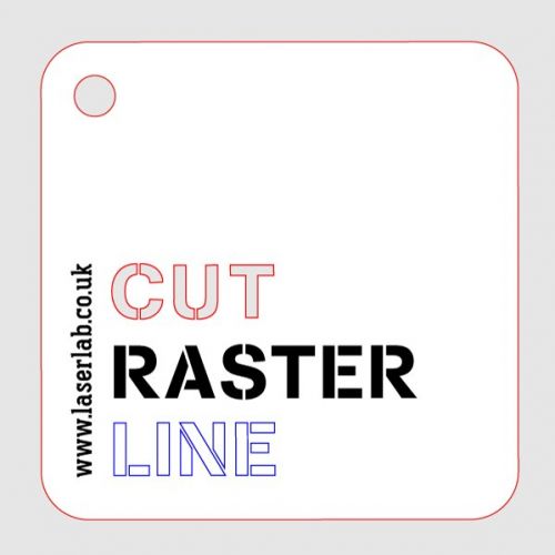
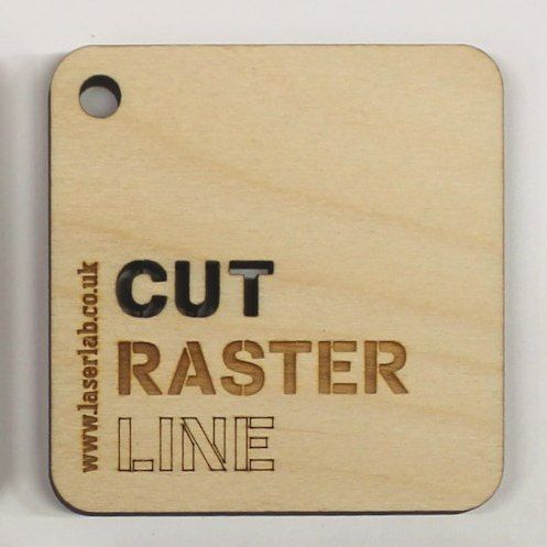
Cut Lines. All cut geometry should be designed in a single colour (RED - RGB Value 255,0,0), line weight (thickness) should be set to ‘hairline’ (Corel Draw), 0.1pt (Adobe Illustrator) or approx 0.1mm (general CAD software).

Line Engrave (also called Vector Engrave). Line engrave relates to a single pass of the laser at the centreline of geometry, it is the same process as laser cutting but is at a reduced power. Typically line engraving can produce a maximum marking width of 1mm. Engraving should be distinguished from cut geometry by either layering your design (e.g. Layer 1 – cut profiles, Layer 2 - line engrave), or geometry can be coloured to clarify requirement, RED = cut, BLUE (RGB Value 0,0,255) = line engrave. Line thicknesses in your design should be the same as for cut lines (0.1pt/0.1mm), all other blue lines (and fills) will be ignored by the laser.

Raster Engrave (also called Filled or Scan Engraving). Relates to multiple zig-zag passes of the laser between geometry lines creating a filled effect. This process is very slow in comparison to cutting and is normally subject to a surcharge. Raster engraving should be distinguished on a separate layer (e.g. Layer 1 – cut profiles, Layer 2 - line engrave, Layer 3 - raster engrave), or geometry can be coloured to clarify requirement, RED = cut, BLUE = line engrave, BLACK = raster engrave (RGB Value 0,0,0).
Example File Design and Output
File Templates
The following templates provide a useful guide to creating your first laser file.
- Sample design file, (Adobe Illustrator).
- Sample print and cut file, (Adobe Illustrator, for use with our laser vision system).
File Layouts
|
|
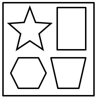
Good Sheet Layout Cut shapes in the centre of the material with gaps between parts. We recommend a minimum gap between parts of 3mm (laser), 5mm (plasma) or 1/3 of the material thickness (whichever is greater). |
|
|
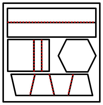
Shared Cut Lines No gaps between parts, not recommended. Parts susceptible to distortion (due to heat expansion) and a common cause of inferior parts / geometry errors due to duplicate lines. Typically caused by trying to fit too much on an available sheet size. |
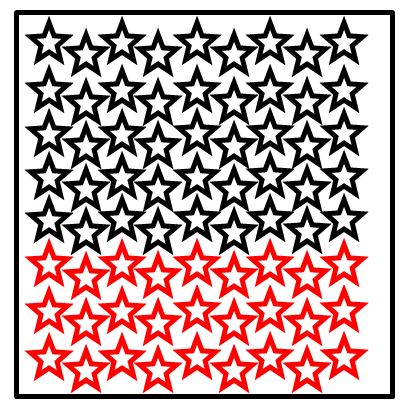 |
Too Many Items Our listing pages give an instant price inclusive of material and cutting. This price is independent of the design file uploaded to cut but we do stipulate that design files of over 50 parts (Laser) on a single sheet must first be sent for review and may be subject to a surcharge due the increased processing time (please use the upload link on our contact page). Metal (Plasma) cutting prices are for a SINGLE part only. Internal cut-outs/holes do not count to the part count. |
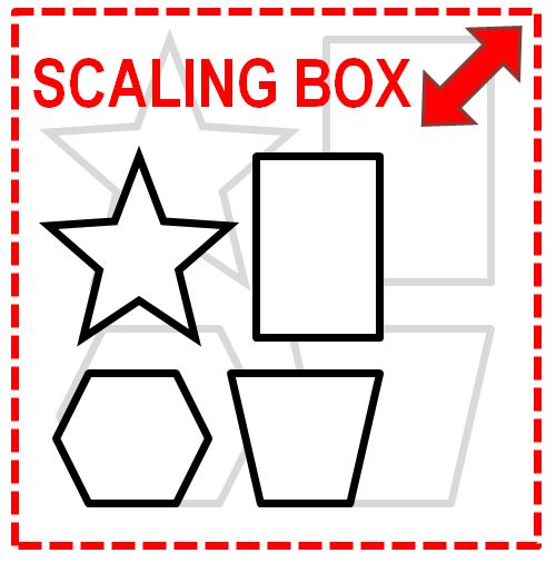 |
Unfortunately not all file formats and software version are equal. Files created 1:1 (or with 100% scaling) can export/import at different sizes depending on software version. This is typically an issue with vector files created by graphic programs such as Inkscape (SVG) and Illustrator (AI), (CAD output DXF or DWG is usually more reliable though issues can exist with units mm / in / px / dpi). To ensure files are imported correctly please include an outer border/bounding box to your design file that matches the selected sheet size, this can be any colour (e.g. if you select a sheet size of 300 x 300mm please include a square on your design file at this size so we can be confident the file is scaled correctly). |
|
|
Oversized Profiles Please ensure your geometry file meets the maximum size criteria on our product listing pages (width x length). Design files that do not meet the size criteria may be rejected or cause a delay in the processing of your order. In all instances please contact us if you have a query about your file before placing an order. |
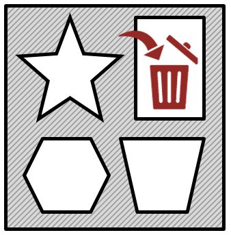 |
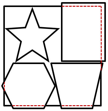
Offcuts Sheet material outside of the cut geometry is discarded (and will not be shipped with your order). If your design does not utilise the full sheet available we suggest including rectangles (red lines) in the excess areas to keep this material. Note please do not place an order and include a comment stating 'keep all offcuts', it is typically not practical to ship the excess material as it is too fragile to post (or incurs excess postage costs). If your require the outer shape (e.g. for a template) please include a cut line inside of the sheet size (min, 2mm all round). If in doubt please email before placing an order. |
Size & Cutting Limitations
We have 2 lasers and 1 plasma cutter, cutting sizes outlined below (we can also accommodate larger sheet materials via a bypass hatch). Size limitations can also relate to the sheet materials available to us (refer to product pages for available sizes).
- RS Laser [machine currently unavilable] - 1200mm x 900mm, cutting power 100W (CO2, glass tube laser source).
- Trotec Laser - Speedy 400 - 1000mm x 600mm, cutting power 120W (CO2, ceramic tube laser source). Includes Vision system and Rotary axis.
- Swift-Cut (Plasma) - 1200mm x 1200mm, cutting power 45A (with water table and pneumatic engraver). For further details regarding plasma cutting and preparing your artwork please see our plasma guide.
Materials to Cut & Engrave
We can process many materials as listed below and are happy to try further materials on request.
- Laser cutting and engraving - Acrylic, Perspex, Plastics, PVC, Glass, Acrylic Mirror, Leather, Slate, Stone, Paper, Granite, Wood, Cork, Glass, Crystal, Garments, Denim, Paper, Leather, Rubber, Stones, Ceramic, Gaskets, Mobile phones.
- Plasma cutting - Steel (mild / galvanised and stainless), Aluminium, Copper and Brass.
We can also engrave many metals just ask for further details. For examples see our materials page.
Cutting Width (Kerf) & Material Thickness Tolerances
Cutting width or kerf relates to the width of the groove made when cutting. For laser cutting this is very narrow but it needs to be considered when parts are deigned to slot or fit together. With reference to the picture below designing a jigsaw without considering the kerf width would make the joints loose. To compensate you can offset the design by half the known kerf width (where known this is detailed on the material listing pages). Example below has a kerf width of 0.2mm, so you should look to design your part oversized by 0.1mm (all round) to compensate.
The thickness tolerance of the material can also effect fit, man-made materials can have a surprisingly large tolerance, (e.g.cast acrylic +/-15% of stated size), in all instances we recommend trials before committing to a large production batch of cuts for interlocking parts.
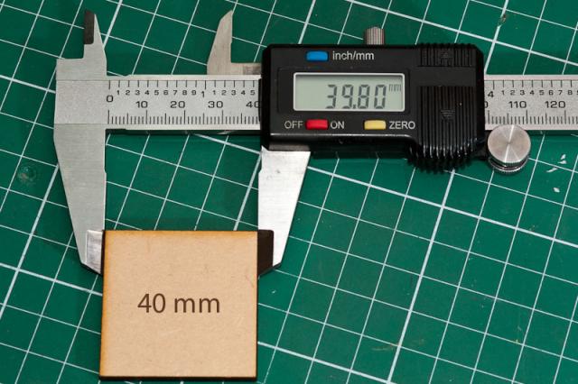
Measuring Kerf

Fit Issues When Not Considering Kerf
Additional Resources & Useful Links
- Selected supplier list and resources list coming soon.
